REVERSE ENGINEERING: Make Waves Instrument No. 7148 - "SuperPro" Dual Function Computer Decoder


Background
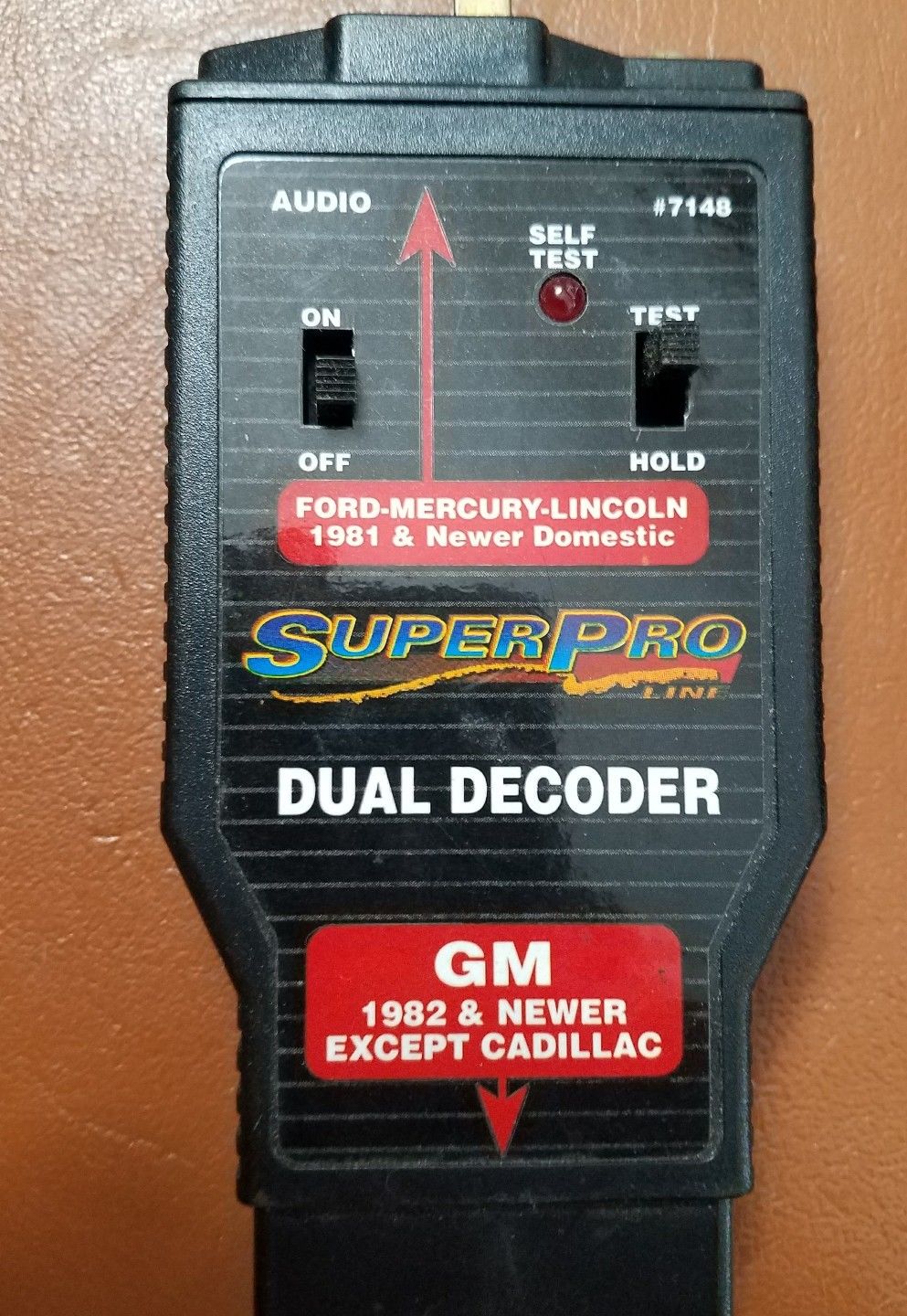
I was helping somebody troubleshoot vehicle diagnostic codes on their circa ‘84 Mustang. They had attempted using a device that goes by the name of “SuperPro Dual Function Computer Decoder”. This is an old-ish device whose construction is quite simple.
What prompted this endeavor was an interesting failure mode: Smoke began to pour out of the device when it was operated per-instructions. The vehicle’s self-test input connector was shorted internally to the battery voltage. Not entirely sure why that is (input protection/clamping diodes?).
Taking it apart
When it doubt: tear it down, right? The simple nature of the device made it expectedly easy to take apart. Inside is a single circuit board, a 9V battery, and wires going off to the diagnostic connector on the unit. Quickly noticed was the burnt-up low-value resistor. It was tricky to read at first, and I’m still not sure after looking at its remains under a microscope; but I believe it was a 35.5 ohm resistor (odd, right?).
Capturing the schematic
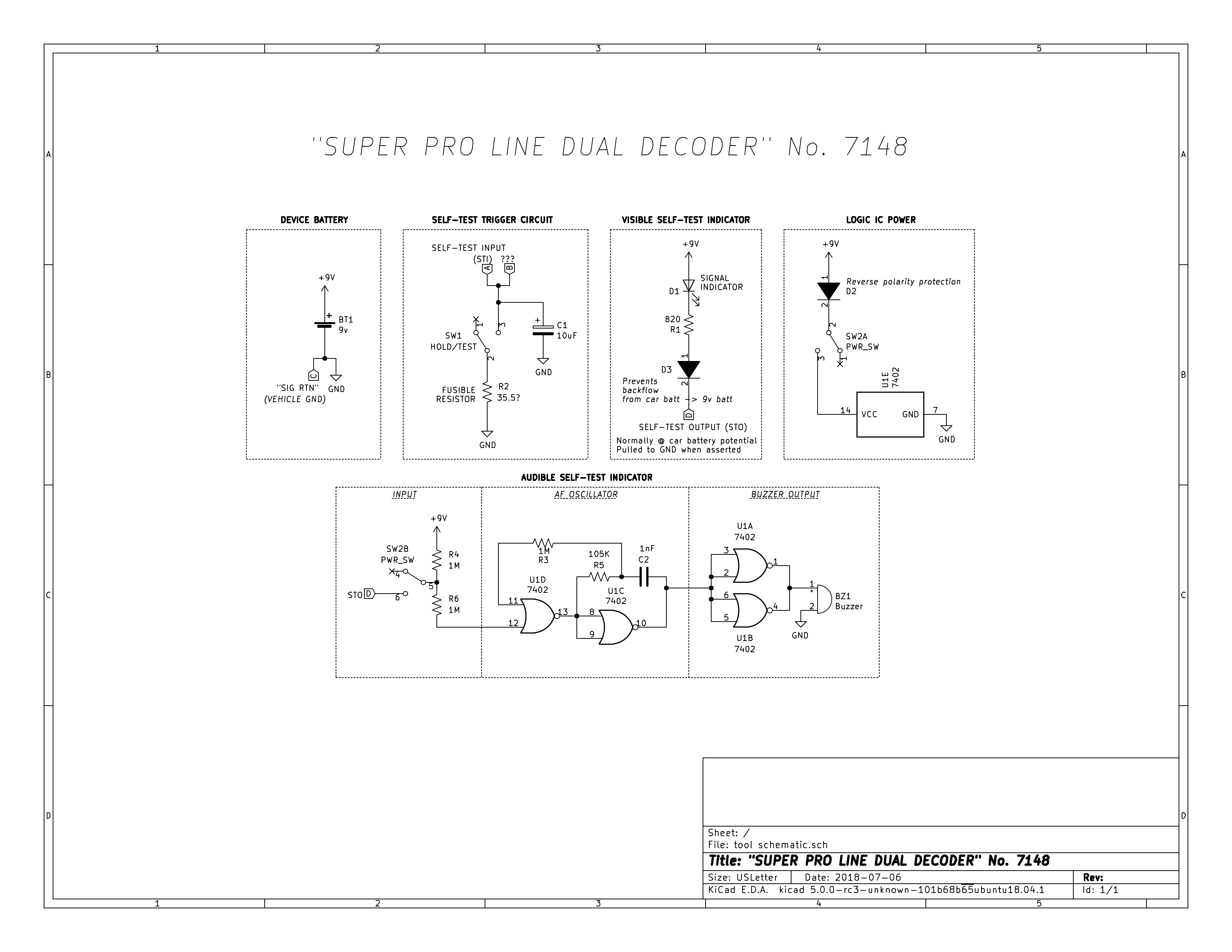
I was unaware of the malfunctioning vehicle ECU at the time, and I was curious as to why this resistor burnt up. It would have been a simple case of tracing out where this resistor is attached to to identify the problem. But I was also curious why this circuit board had a quad-NAND gate IC and seemingly more components than would be necessary for the task it performs. This prompted a full schematic capture of the (relatively simple) device.
Diagnosis
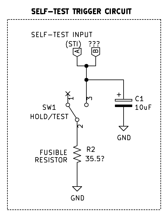
When looking at just the self-test trigger circuit on the decoder, it becomes evident that there must have been a high enough voltage across the resistor to exceed its power rating. This was verified by measuring the self-test input (STI) pin on the vehicle when loaded by a 1K resistor. It was at the car’s battery voltage. I believe the purpose of this resistor R2, as annotated in the schematic, is to prevent other parts of the circuit from going up in flames if there was a faulty STI or if the user connected the device incorrectly.
Conclusions
I’m not really sure what the purpose of C1 in the self-test trigger circuit is.
It’s interesting that on the board is an oscillator for the audible indicator. I suppose the piezoelectric buzzers available nowadays with their built-in oscillators were not available then or were too expensive. This oscillator circuit is probably the main reason there even is a PCB in the device.
A deeper inspection will be necessary to understand what caused the malfunction on the vehicle side (possibly somewhere inside the engine control unit).
I wanted to share this schematic because I hope that it or the experience had along with it may help somebody else.